How to read an automotive wiring diagram
A methodical way to trace an automotive circuit without confusing a schematic with the vehicle's physical wire layout.

An automotive wiring diagram explains electrical relationships. It shows which points are connected and how a circuit is meant to operate. It may not show where every wire physically runs through the vehicle.
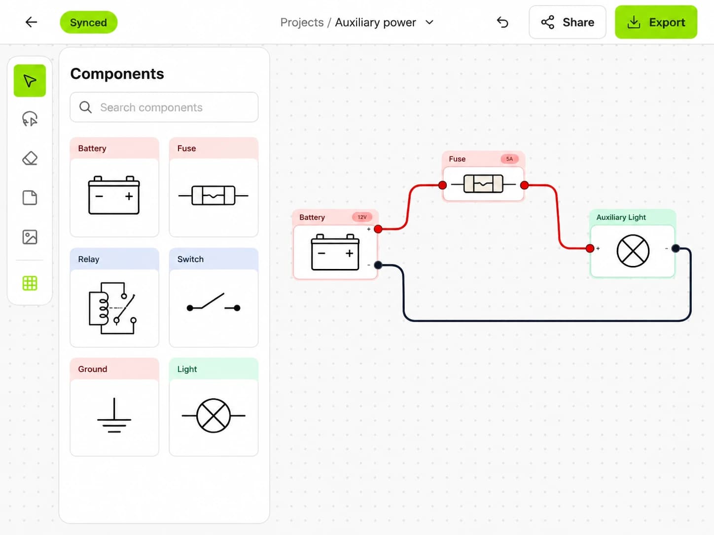
The easiest way to read one is to stop treating the whole page as a single puzzle. Pick one load, find its power and ground, then trace the control path that lets it operate.
Read the title and legend first
Confirm the vehicle, model, option package and circuit covered by the page. A diagram for a base model may not match a vehicle fitted with a body control module, tow package or different engine.
Use the legend supplied with that manual. Symbol shapes, dashed boxes, connector notation and wire-colour abbreviations vary between publishers. Do not carry an abbreviation from one manufacturer's manual into another without checking it.
Also note whether the page is a schematic, connector view, harness layout or ground-location drawing. You may need more than one of these to find and test the physical circuit.
Trace the load path
Choose the component that is not working, such as a lamp, fan or horn. Work through this order:
- Find the power source.
- Identify the fuse or circuit protection.
- Follow the feed through switches, relay contacts and connectors.
- Find the load.
- Follow the return path to ground or the controlling module.
Mark each connector and splice as you pass it. A line crossing is not always a connection; the diagram's junction symbol decides that. Page references may send the circuit to another sheet, so record where it leaves and where it returns.
Power is not always present just because the line starts at a battery symbol. Labels such as battery, accessory, ignition and start describe different switch states. A module-controlled output may also switch power or ground only when its operating conditions are met.
Separate the control and load circuits
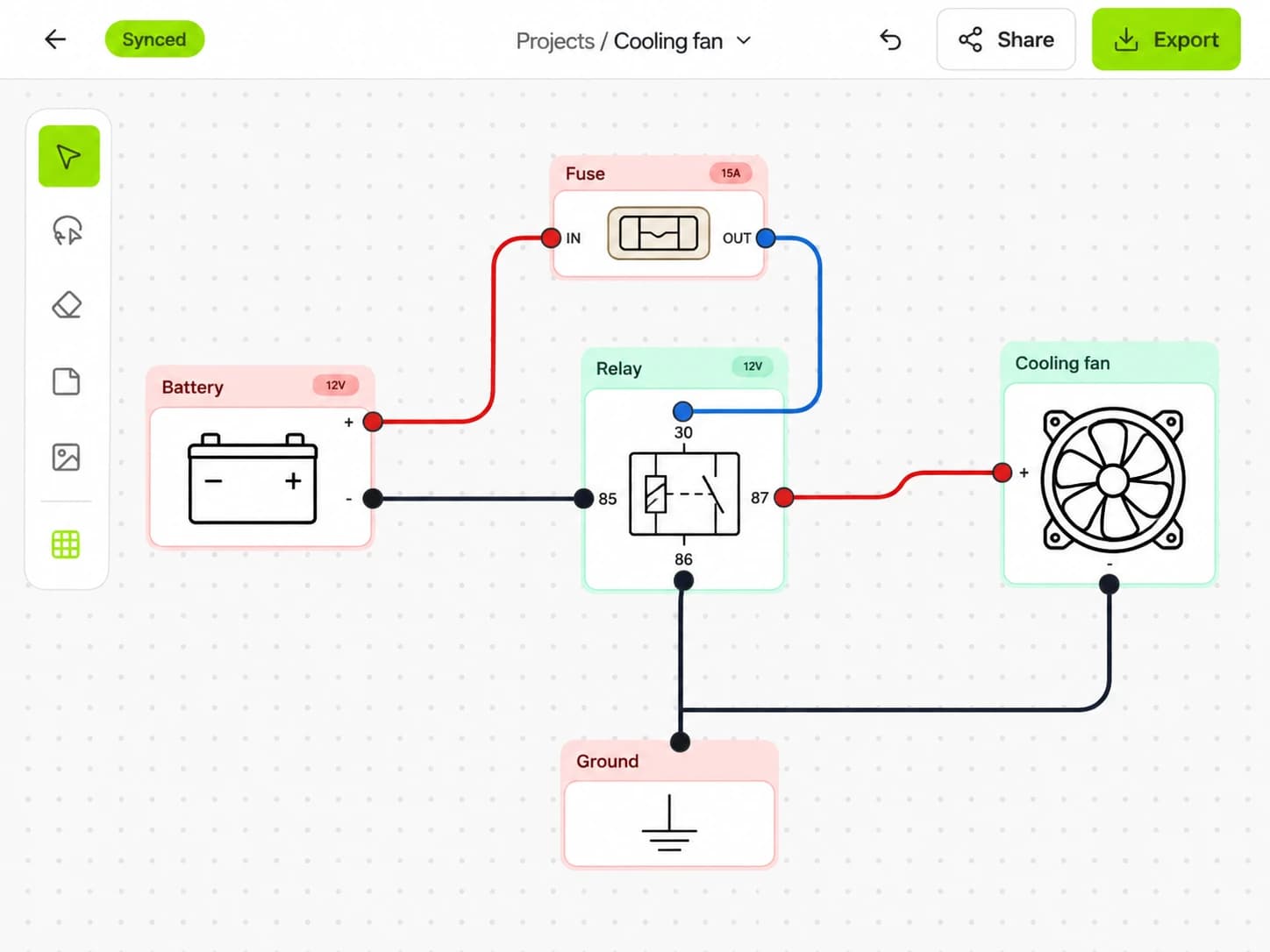
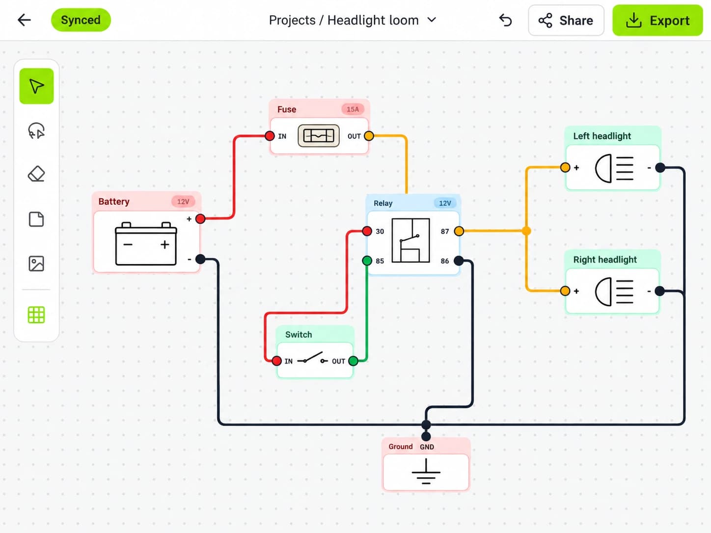
A relay diagram becomes easier when you split it into two circuits. The coil is the control side. The contacts carry current to the load.
In the common relay layouts documented by this HELLA relay guide, terminals 85 and 86 are the coil connections, terminal 30 is the load-current input, terminal 87 is the normally open output and 87a is the normally closed output on a change-over relay.
Treat those numbers as a reading aid, not permission to wire by memory. Check the diagram printed on the relay and its datasheet. Relays with diode suppression can require the coil to be connected with the correct polarity, and specialised relays may use a different internal arrangement.
When a relay will not energise, trace the coil circuit first. When it clicks but the load stays off, trace the contact feed, output and load ground. A click confirms movement; it does not prove that the contacts carry current with an acceptable voltage drop.
Decode wire and connector labels
A useful wire label can contain a circuit number, colour, size and destination. The exact order depends on the manual. Connector identifiers normally pair with pin or cavity numbers, which let you move from a schematic to a connector view.
Do not assume every wire keeps the same colour through a connector or replacement harness. Verify the cavity and circuit reference. Splices can feed several loads from one conductor, and a fault upstream of the splice can affect all branches.
Ground symbols also need context. Several ground symbols on a page may join at one physical stud, or they may be separate points in different parts of the body. Use the ground-location information before testing continuity to the nearest piece of metal.
Turn the diagram into test points
Once the route is clear, choose test points that divide the circuit. A fuse output, relay input, relay output, load connector and ground connection form a useful sequence. Test under the operating condition in which the fault occurs.
A voltage reading with the load disconnected can be misleading because a damaged connection may pass enough current for a meter but not for the component. Voltage-drop testing across connections while the circuit is loaded can expose resistance that a simple continuity check misses.
Follow the service manual before back-probing connectors or disconnecting modules. Airbag, hybrid and electric-vehicle circuits require their specified isolation and test procedures.
Redraw only what you need
For a modification or fault note, copy the relevant circuit into a smaller working diagram. Keep the fuse, relay contacts, control path, connector IDs, load and ground. Add verified wire colours and pin numbers, but do not invent missing details.
For the next step, see how to make a simplified wiring diagram and how to label automotive wires.
X/D Loom can be used to turn that traced circuit into a labelled workshop diagram. The source service information remains the authority. The redrawn page is there to make the route easier to understand, install and revisit later.
Put it into practice.
Plan your next circuit in X/D Loom. Add components, connect the wires, and keep your build easy to follow.
Free to start. No credit card required.