Automotive Relay Types: SPST vs SPDT
Automotive relay types explained: SPST, SPDT, 4-pin, 5-pin, changeover, latching, diode, resistor, and solid-state relays.
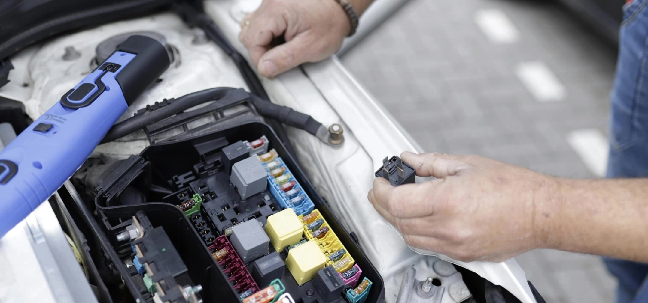
Relays look simple, but picking the wrong one can make a circuit fail in odd ways. This guide explains the main automotive relay types, including SPST vs SPDT, 4-pin vs 5-pin, diode and resistor relays, latching relays, and solid-state relays.
A relay is an electric switch. A small control circuit powers a coil. That coil moves a contact, which switches a larger load. In vehicles, relays let a low-current switch, ECU output, or sensor control lights, fans, horns, pumps, compressors, and other high-current devices.
The trick is knowing what happens inside the relay before you plug it in.
Why vehicles use relays
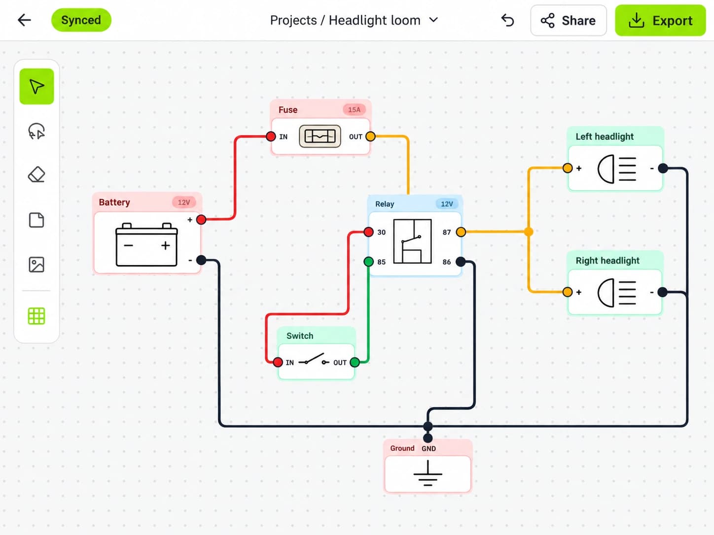
A relay keeps high current out of places where it does not belong. For example, a dashboard switch may only be safe for a few amps, while a pair of driving lights may pull much more. Instead of sending lamp current through the dashboard, the switch energizes a relay coil. The relay then feeds the lamps from a fused battery supply.
Relays help with shorter high-current cable runs, lower voltage drop at loads, smaller control wires, ECU-safe switching, and cleaner fault finding. They do not replace fuses. The feed to terminal 30 still needs fuse protection sized for the wire and load. If you are laying out a new fuse panel, this pairs well with the guide to the Fuse Box of a Car: Your Complete Guide for 2026.
Automotive relay types: SPST vs SPDT
SPST and SPDT describe the contact layout inside the relay.
- SPST means single pole, single throw.
- SPDT means single pole, double throw.
“Pole” is the common moving contact. “Throw” is the output path it can connect to.
SPST relay: simple on/off control
An SPST relay is a basic on/off switch. It has one input contact and one output contact. When the coil turns on, the relay connects them. When the coil turns off, it opens them.
Most common 4-pin automotive relays are SPST normally open relays.
Typical terminals:
Terminal | Common function |
|---|---|
85 | Coil side |
86 | Coil side |
30 | Power input or common contact |
87 | Switched output, normally open |
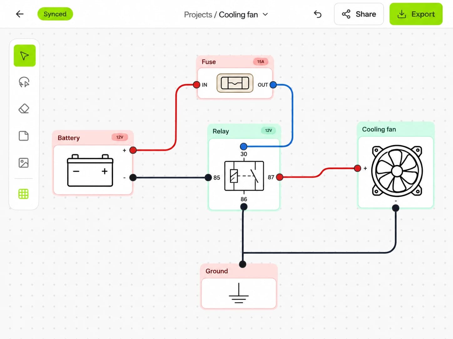
Use SPST relays for driving lights, horns, fans, fuel pumps, compressors, heated seats, and work lights. In most cases, battery or fuse box power enters terminal 30, the load connects to terminal 87, and the coil uses terminals 85 and 86.
SPDT relay: changeover control
An SPDT relay has one common contact and two output paths. One path is connected when the coil is off. The other path is connected when the coil is on.
Typical terminals:
Terminal | Common function |
|---|---|
85 | Coil side |
86 | Coil side |
30 | Common contact |
87 | Normally open output |
87a | Normally closed output |
With the coil off, terminal 30 connects to 87a. With the coil on, terminal 30 connects to 87. Use SPDT relays when you need to switch between two states, interrupt a circuit when another circuit becomes active, reverse polarity with two relays, or build starter inhibit and alarm interrupt circuits.
The key point: 87a is live when the relay is at rest if terminal 30 is fed.

4-pin vs 5-pin relays
Pin count helps, but it does not tell the full story.
Relay style | Usually means | Main use |
|---|---|---|
4-pin | SPST normally open | Turn a load on and off |
5-pin with 87a | SPDT changeover | Switch between two outputs |
5-pin with two 87 terminals | SPST with dual outputs | Feed two loads at once |
Some 5-pin relays have terminals marked 87 and 87, not 87 and 87a. These are not changeover relays. Both 87 terminals turn on together, so they cannot provide a normally closed circuit.
Always check the small diagram on the relay case or the datasheet. Do not rely on pin count alone.
Normally open vs normally closed
Relay contacts have a resting state. “Resting” means the coil is not powered.
- Normally open (NO): open at rest, closed when energized.
- Normally closed (NC): closed at rest, open when energized.
A standard SPST relay is often NO. A changeover SPDT relay gives you both: 87 is NO, and 87a is NC.
Use NO contacts when a load should be off by default, such as auxiliary lights. Use NC contacts when a circuit should work until the relay is triggered, such as some alarm interrupts. Be careful with NC circuits: if the coil wire breaks, the circuit returns to its resting state, which may or may not be safe.
Relay coil voltage: 12V, 24V, and control side details
The coil voltage must match the control system. A 12V coil belongs in a 12V circuit. A 24V coil belongs in a 24V truck, boat, or commercial system.
The contact rating is separate from the coil rating. A relay may have a 12V coil and contacts that can switch a higher voltage or current within its rating. You still need to check the relay’s data.
Coil terminals are usually 85 and 86. On a plain relay, polarity often does not matter. On a relay with a diode or LED inside, polarity does matter.
Diode-suppressed and resistor-suppressed relays
When a relay coil turns off, its magnetic field collapses. This can create a voltage spike, often called flyback. Suppressed relays reduce that spike, which matters when an ECU, module, or transistor controls the coil.
Diode relay
A diode across the coil clamps the spike and provides strong suppression. The downside is that coil polarity matters. A diode relay wired backward may blow a fuse, damage a driver, or short through the diode.
If a relay has a diode, wire 85 and 86 as shown on the relay’s diagram. Do not guess.
Resistor relay
A resistor across the coil also reduces flyback, but it is usually not polarity sensitive. That makes it useful in mixed ground-switch and positive-switch layouts.
A resistor may not suppress the spike as strongly as a diode, so always check the vehicle manual or module instructions.
Micro, mini, ISO, and cube relays
Many automotive relays follow common terminal patterns, often based on ISO-style numbering. That makes replacements easier, but housings and pin sizes still vary.
Common physical types include mini ISO cube relays, micro relays, high-current relays, sealed relays, and PCB-mounted relays inside modules. Match the socket, terminal size, current rating, and environment. Do not force a relay into a socket because “the pins almost line up.”
For terminal numbering, the DIN 72552 overview is a useful reference, though real vehicles may add their own details.
Special automotive relay types
SPST and SPDT cover most jobs, but vehicles also use more specific relay types.
Latching relay
A latching relay changes state and stays there without continuous coil power. Some use one coil. Others use separate set and reset coils. They are useful for battery isolation or camper control circuits, but they need a clear control plan because the last state may remain after power loss.
Time-delay relay
A time-delay relay waits before turning on or off. It can run a fan after shutdown, delay accessory power, or prevent rapid cycling. Check whether the delay applies on energize, de-energize, or both.
Flasher relay
A flasher relay cycles a lamp circuit on and off. Older units depend on load current, while newer electronic units are less load-sensitive. LED indicator conversions often need an electronic flasher or added load, depending on the vehicle.
Solid-state relay
A solid-state relay has no moving contact. It uses electronics to switch the load. Solid-state relays can be silent, fast, and resistant to contact wear, but heat management matters. Some also leak a tiny off-state current, and their failure modes differ from mechanical relays.
Use the datasheet. Solid-state relays are not drop-in replacements in every circuit.
Starter relay and solenoid
Starter circuits often use a relay, a solenoid, or both. A starter solenoid is a heavy-duty electromagnetic switch that can also move the starter drive gear. Do not treat a small cube relay as a starter solenoid.
Continuous-duty solenoid
A continuous-duty solenoid is built to stay energized for long periods. It is common in dual-battery, winch control, and auxiliary power systems. A starter solenoid may handle high current for a short burst, but may overheat if held on.

How to choose the right relay
Once you know the main automotive relay types, use this checklist before you add one to a loom:
- Define the load. Is it a lamp, motor, pump, heater, solenoid, or electronic module?
- Find steady current and inrush current. Motors and lamps can draw more at startup.
- Choose contact form. Use SPST for simple on/off. Use SPDT for changeover or interrupt circuits.
- Match coil voltage. Use 12V relays in 12V systems and 24V relays in 24V systems.
- Check contact rating. Use a relay rated for the load type, not just the amp number.
- Pick suppression if needed. Use diode or resistor suppression for sensitive control circuits.
- Choose the environment rating. Use sealed parts in wet, dusty, or engine-bay locations.
- Plan the fuse. Fuse the supply to terminal 30 based on the wire and load.
- Check socket quality. Loose terminals create heat and voltage drop.
- Document the terminals. Future fault finding depends on clear labels.
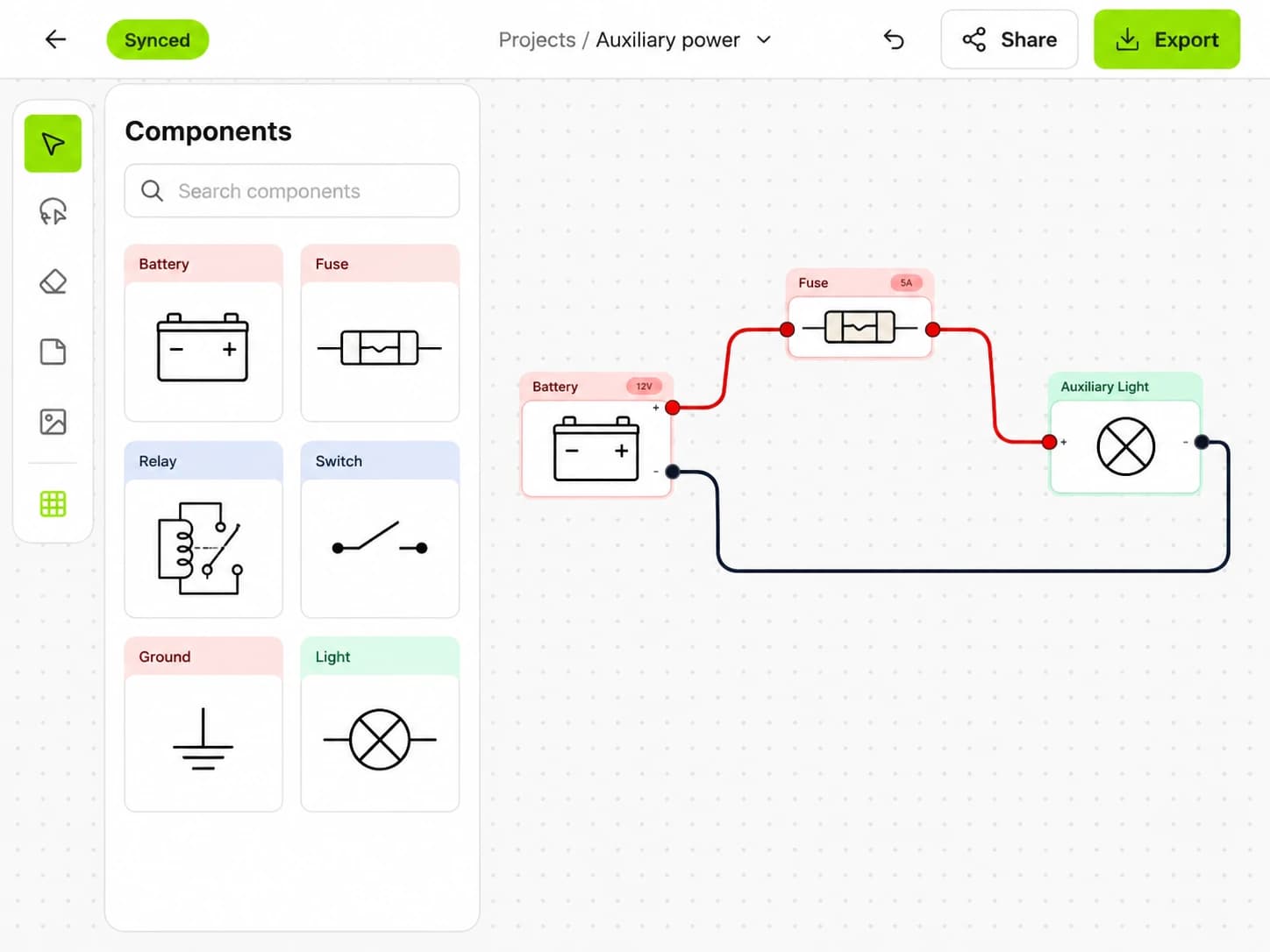
X/D Loom can help here because you can draw the relay, fuse, wire size, connector, and load in one place. That makes it easier to spot an unfused feed or a wrong 87a connection before the loom is built. If you are comparing diagram tools, see Automotive Wiring Diagram Software: X/D Loom vs SmartDraw.
Common relay wiring mistakes
Even when the automotive relay types are understood, most faults come from a short list of errors:
- Mixing up 87 and 87a. If a load is on when it should be off, check whether it is connected to 87a.
- Assuming every 5-pin relay is SPDT. Some have two 87 outputs and no normally closed contact.
- Forgetting coil suppression polarity. A diode relay wired backward may blow a fuse or damage a driver.
- Switching too much current through a small socket. The relay, socket, terminals, and wire all need to suit the load.
- Leaving terminal 30 unfused. A relay does not protect the wire.
Quick testing guide
You can bench test many mechanical relays with a fused power source and a multimeter.
Basic steps:
- Identify the coil terminals.
- Apply the correct coil voltage through a fuse.
- Listen or feel for a click.
- Check continuity between 30 and 87.
- For SPDT, check that 30 and 87a connect at rest.
- Remove coil power and confirm it returns to rest.
A click does not prove the relay can carry load current. Contacts can be burnt or high resistance. If a circuit fails only under load, measure voltage drop across the relay contacts while the load is on.
Conclusion
Understanding automotive relay types comes down to contact form, coil voltage, contact rating, suppression, duty cycle, socket quality, and environment. SPST relays switch one output on and off. SPDT relays switch a common contact between normally closed and normally open outputs.
Before you crimp the loom, draw the circuit and mark each relay terminal clearly. Build your next relay layout in X/D Loom so the fuse, relay, wires, and loads all make sense before power is applied.
Put it into practice.
Plan your next circuit in X/D Loom. Add components, connect the wires, and keep your build easy to follow.
Free to start. No credit card required.